


Photo: The robotic engineer1 / Wikimedia Commons, CC BY-SA 4.0.
Quick answer
Start a custom injection molding project by defining the part before authorizing the mold. Send a controlled 3D CAD model, a 2D requirements drawing, the exact resin or performance target, annual and peak volume, critical dimensions, cosmetic zones, compliance needs, and pass/fail tests. Approve DFM and the mold concept, inspect traceable first samples, then validate a repeatable production process and packaging system. A CAD file by itself is not a complete production specification.
First decision
What must pass?
Turn needs into measurable tests.
Best quote input
CAD + drawing
Geometry plus controlled requirements.
Cost control
Freeze by gate
Resolve risk before cutting steel.
Production rule
Evidence, not T1
First samples are a learning event.
This guide is for product developers, engineers, sourcing managers, quality teams, and OEM buyers moving a thermoplastic part from prototype into repeat production. Controlled sectors need additional customer and regulatory requirements defined at project start.
Build a quotable package before you ask for tooling
The real starting point is a controlled product definition. Words such as strong, premium, sicuro per gli alimenti, O tight fit are useful goals, but a molder cannot inspect them. Translate each important need into a condition and pass/fail result: load and deflection, temperature and exposure time, leak rate, assembly force, service cycles, visible-surface limits, mating-part fit, or a named compliance route.
Separate requirements from preferences. A sealing diameter, electrical clearance, snap life, or customer-visible color may control acceptance. A hidden gate, target piece price, or optional texture may be negotiable. If everything is critical, the supplier cannot focus effort where failure matters most.
Minimum RFQ package
- Part definition: clean 3D CAD, controlled 2D drawing, revision, units, datums, critical features, mating information, and file hierarchy.
- Use conditions: loads, temperature, chemicals, UV, moisture, service life, cleaning, storage, transport, and realistic misuse.
- Material and appearance: exact grade or approval route, color, additives, texture, finish, visible zones, and acceptable molding witnesses.
- Demand: prototypes, launch quantity, annual forecast, peak-month rate, batch size, lifetime volume, and delivery region.
- Approval: dimensional, functional, cosmetic, material, compliance, packaging, capability, and customer-submission deliverables.
- Commercial control: tool ownership, maintenance, storage, transfer, confidentiality, data rights, payment gates, and change terms.
Part geometry, function, interfaces, material, and inspection requirements need to tell one consistent story.
Use five approval gates from requirements to production
A project can move quickly without becoming vague. Each gate should name the released revision, evidence reviewed, open risks, owner, decision, and revalidation required after a change. The table below is deliberately short so it remains readable on a phone and useful in a kickoff meeting.
Approval means the evidence supports the next commitment. It does not erase recorded residual risk.
Step 1: define function, environment, volume, and acceptance
Describe the part inside its product, not as an isolated shape. Provide assembly CAD or mating samples, load cases, seal or snap behavior, clearances, fastening, service cycles, and failure criteria. Record temperature, humidity, chemicals, UV, cleaning, storage, and transport. A room-temperature prototype may creep when warm, become brittle when cold, swell with moisture, or crack after chemical exposure.
Give launch, annual, peak-month, lifetime, and service-part volume scenarios. Peak rate drives cavity count, press capacity, labor, automation, packaging, safety stock, and contingency. State forecast uncertainty: a single-cavity bridge tool and a hardened multi-cavity production tool solve different risks.
Funzionale
Fit, seal, load, torque, snap, drop, fatigue, or optical/electrical behavior.
Cosmetic
Named visible zones, lighting, viewing distance, color master, and defect limits.
Commerciale
Forecast range, launch window, delivery lane, inventory policy, and change flexibility.
Step 2: choose a material grade, not just a resin family
PP, ABS, PC, PA, POM, PBT, and TPE describe broad families. Grade, melt behavior, reinforcement, UV or flame package, colorant, recycled content, conditioning, and source can change molding and performance. Select against the actual stiffness, impact, creep, heat, chemical, fatigue, weathering, electrical, compliance, and cost needs.
Where performance or certification matters, name the producer, grade, color or masterbatch, additive limits, permitted regrind or recycled content, drying, conditioning, and substitution rule. Define how alternates will be reviewed and retested. Test-bar datasheets do not automatically predict a finished part with its weld lines, orientation, wall transitions, residual stress, color, and process history.
A project needs an exact, approved material specification. For flame-controlled electrical products, a UL Yellow Card applies to the listed material and conditions; it is not blanket approval of the finished molded assembly.
Step 3: control CAD, drawings, tolerances, and measurement
Use a clean native or neutral 3D solid for geometry and a controlled drawing or product-definition document for requirements. State revision, units, datums, critical characteristics, material, finish, texture, color, inspection notes, and which document wins if files conflict. Apply tight tolerances only where function, assembly, safety, or compliance requires them.
Plastic dimensions respond to flow orientation, shrinkage, packing, cooling, restraint, moisture, time, and temperature. Define when and how a critical dimension is measured: conditioning time, environment, free-state or restrained condition, fixture, datum setup, and contact or optical method. ISO 20457:2026 is the current edition for molded-part dimensional and geometrical tolerances and acceptance conditions; it still does not cover cosmetic imperfections such as sink, flow structures, roughness, and joint lines. Lock the governing standard and edition in the contract rather than relying on a generic tolerance note.

Digital review helps teams see part, mold, and access decisions together. Image: TechDesign23 / Wikimedia Commons, CC BY-SA 4.0.
Step 4: prototype to answer a named risk
Choose the prototype process by the question. A 3D print can reveal envelope, access, interference, hand feel, and assembly order. CNC machining can support fit or load learning in some engineering plastics. Neither automatically reproduces molded shrinkage, fiber orientation, weld lines, gate effects, residual stress, surface, or cycle conditions.
Use bridge or prototype tooling when the decisive risk needs the production resin and a molding process. Even then, differences in tool metal, cavities, runner, cooling, gate, machine, or settings can limit what the evidence proves about the final tool. On every prototype report, write two lines: “This validates…” and “This does not validate…”. That prevents a visually accurate sample from being mistaken for production proof.
Step 5: make DFM a joint engineering review
Injection molding DFM should explain how the part, resin, mold, machine, and process interact. Review wall thickness and transitions, radii, ribs, bosses, draft, texture, undercuts, parting line, shutoffs, gates, runners, vents, weld lines, cooling, shrinkage, warpage, and ejection. For each risk, record the affected requirement, proposed action, accepted limitation, and evidence still needed.
Rules of thumb are conversation starters, not universal acceptance criteria. Required draft changes with surface depth, texture, polish, resin shrinkage, core geometry, and ejection. Rib and boss proportions depend on wall, material, load, sink visibility, flow, and fastening. A generic shrink percentage cannot guarantee every finished dimension. Ask the selected molder to review the actual feature with the intended grade and tool concept.
Fill and pack
Gate location, flow length, pressure, weld lines, air traps, sink, and vestige.
Cool and move
Wall transitions, cooling balance, shrinkage, fiber direction, and warpage.
Open and eject
Draft, texture, undercuts, slides, lifters, pins, witness marks, and distortion.
Simulation becomes more valuable when thin walls, long flow, multiple cavities or gates, fiber orientation, cosmetics, cooling, or warpage create meaningful risk. Autodesk Moldflow can explore filling, packing, cooling, deflection, weld lines, sink, gating, and material/process choices. Results depend on the model, material data, and inputs; trials must confirm the real mold and process.
Step 6: choose tooling for lifetime cost and risk
Do not choose mold metal, cavities, runner, family molding, or actions from annual volume alone. Consider peak rate, lifetime demand, resin and fillers, press availability, cosmetics, change uncertainty, maintenance, interruption cost, and transferability. Tie quoted tool life to the exact alloy, inserts, resin, cycle, maintenance, wear limit, repair, and warranty.
More cavities can increase output, but also investment, balance risk, press size, correction work, and inspection. A hot runner may reduce runner waste while adding controls, service, purge, and color-change concerns. A family mold couples components that may later have different demand or revisions. Compare cost per good delivered part.

Cavitation, feed, cooling, ejection, wear, and correction must be reviewed as one tool system. Photo: Bricetofly / Wikimedia Commons, CC0.

Before machining, approve the mold concept, service plan, ownership terms, and correction strategy against the same released part revision.
Step 7: compare injection molding quotes on equal scope
One quotation may include inserts, simulation, layouts, sample loops, maintenance, packaging, and shipping while another includes a basic mold and nominal part price. Normalize assumptions before ranking price. Require inclusions, exclusions, customer inputs, process location, subcontracted work, capacity basis, and change charges.
The lowest tool quote may carry the highest project cost
Check resin basis, expected yield, cycle assumptions, setup, inspection, secondary operations, sample quantities, correction loops, mold maintenance, spare parts, packaging, freight, storage, ownership, and transfer. Missing scope usually returns later as delay, change cost, or unplanned buyer responsibility.
Evaluate the supplier’s engineering response, similar-resin and geometry experience, intended press and auxiliaries, metrology, quality system, tool maintenance, capacity, communication, and business continuity. Ask who designs and builds the mold, where it will be sampled and run, which work is subcontracted, and what happens if the tool must transfer. Certification supports qualification, but it does not prove that this part, tool, process, and measurement method will pass.
Mold ownership is contractual. Define title, asset marking, storage, access, maintenance, insurance, modifications, data ownership, duplicate tools, inactivity, disposal, liens, transfer timing, transfer condition, spares, and shipping. Paying a tooling invoice does not automatically settle every right.
Step 8: approve DFM and mold design before cutting steel
The DFM record should identify the final part revision, resin, shrink basis, draw direction, gate, runner, parting line, actions, ejectors, expected witness marks, cosmetic zones, risks, deviations, and open tests. Then review mold base and inserts, cavity IDs, feed, vents, cooling, actions, interlocks, ejection, wear parts, change inserts, sensors, handling, press interface, utility connections, finish, corrosion protection, spare components, and design-data deliverables.
Confirm which surfaces remain “steel-safe”—able to be adjusted by removing metal rather than requiring material to be added back—and how critical dimensions will be corrected. The purchase order, CAD, drawing, DFM, resin, mold design, deviations, cosmetic standard, and validation plan must all point to compatible revisions. An emailed screenshot is not a dependable tool-release package.
Step 9: treat T1 as evidence, not production approval
T1 often means the first trial samples from a new mold, but suppliers use the term differently. Define the trial objective, resin and color, machine, cavity, sample quantity, process record, tool condition, secondary work, inspection, and shipping. First shots can expose short fill, flash, sink, warp, weld lines, burns, ejection, gate vestige, mismatch, dimensions, assembly, and cosmetics. They do not prove long-run stability or production rate.
Require disclosure of hand trimming, reaming, polishing, annealing, conditioning, fixture restraint, part selection, or unusual settings. A hand-corrected part can still support a fit check, but it must not be presented as normal process output. Review material traceability, all required cavities, a ballooned dimensional report, the defined measurement condition, mating-part assembly, functional tests, controlled cosmetic review, and the action list.

First-sample checking should connect the observed part to its cavity, material, process conditions, inspection method, and disposition.
Step 10: validate measurement, process, packaging, and capacity
A measurement result is useful only when the datum setup, fixture, conditioning, temperature, instrument, program, sample, rounding, and report are aligned. For critical characteristics, confirm that the measurement system can distinguish real part variation from method, fixture, operator, repeatability, and reproducibility effects.
Move from one nominal recipe to a justified process window. Establish the intended machine and mold setup, resin preparation, melt and mold conditions, fill and transfer behavior, pack and hold, cooling, ejection, cycle, auxiliary equipment, startup, shutdown, and reaction plan. Study an appropriate operating range and verify dimensions, function, cosmetics, cavity balance, interventions, and scrap. Capability numbers are meaningful only after the requirement, measurement system, sampling logic, cavity structure, distribution, and process stability are understood.
Run the pilot with production-intent mold, resin, cavities, machine class, auxiliaries, rate, staffing, inspection, secondary operations, and packaging—or document every deviation. Validate warm-part packing, nesting, abrasion, deformation, count, labels, lot identity, stacking, transport, and assembly-line unpacking. A part can leave the press conforming and arrive distorted or contaminated if packaging is treated as an afterthought.

The production release should combine part evidence, process control, traceability, packaging, and agreed response plans.
Match quality and compliance records to the real program
PPAP is a structured production-part approval process used widely in automotive supply chains and wherever the customer contract requires it. It is not a universal legal requirement for every molded part. Other projects may need a first-article report, qualification package, customer-specific submission, or regulated validation route. Define the exact submission level, records, sample quantities, and approval authority instead of using “full PPAP” as a vague synonym for quality.
Food-contact status also cannot be reduced to “FDA-approved plastic.” The FDA explains that each substance reasonably expected to migrate and its authorized conditions of use matter. Exact resin, colorant, additive, processing aid, recycled content, coating, ink, adhesive, insert, food type, time, and temperature may affect the compliance file. Electrical, flame, medical, chemical, and destination-market requirements need the same exact-part discipline.
Acceptance sampling does not replace process control. If an AQL-based plan is used, define lot formation, inspection level, defect classes, AQL, sample scheme, switching rules, critical-defect policy, disposition, and governing edition. “AQL 1.0” without those details is not a usable quality agreement.
Control changes after approval
The approved product is a controlled combination of design, resin, colorant, mold, cavity, process, site, equipment, secondary work, inspection, packaging, and records. A seemingly minor change can alter shrinkage, weld-line strength, gloss, color, moisture response, certification evidence, food-contact status, or assembly.
Write which changes require notice, risk review, samples, tests, capability evidence, customer approval, and master-record updates before implementation. Include CAD and drawing revisions; resin source, grade, additives, regrind, recycled content, or drying; gate, runner, vent, cooling, ejector, texture, weld repair, or duplicate tool; machine, site, auxiliary equipment, process window, cycle, and automation; fixtures, inspection programs, laboratories, sampling, and boundary samples; plus bag, tray, carton, pallet, count, label, warehouse, and transport lane.
Common project failures—and the better control
Quote from CAD only
Function, material, cosmetics, tolerance, validation, and volume become supplier assumptions. Issue one controlled RFQ package.
Tool starts while design moves
Every change affects steel, gate, cooling, inspection, schedule, or tests. Freeze inputs and approve impact before work resumes.
Generic resin selection
The production grade later misses heat, creep, impact, color, shrinkage, or compliance. Select and control the grade early.
Every dimension is tight
Cost rises while priorities disappear. Use functional datums and tolerances; relax noncritical geometry.
T1 becomes approval
Selected parts hide variation, hand work, or unstable settings. Require traceability, reports, function, and process evidence.
Lowest quote wins
Excluded corrections, inspection, maintenance, packaging, or transfer return later. Compare total scope and risk.
Final buyer checklist
- One owner can resolve product, tooling, sourcing, quality, compliance, and launch decisions.
- Requirements cover function, environment, life, appearance, interfaces, demand, compliance, and tests.
- The exact material grade, color/additives, conditioning, substitution, and recycled/regrind rules are controlled.
- CAD, drawing, datums, critical characteristics, cosmetic zones, and mating information share one revision.
- DFM records risks and decisions for wall, draft, ribs, bosses, undercuts, gates, vents, cooling, warp, and ejection.
- Quotes use the same mold, sample, inspection, production, packaging, ownership, storage, and change scope.
- DFM and mold design are approved before irreversible machining.
- T1 and later trials define resin, cavities, quantities, process records, reports, tests, cosmetics, and correction loops.
- Measurement, process window, capacity, packaging, traceability, master records, and change control pass before launch.
Frequently asked questions
What files are needed for an injection molding quote?
Provide controlled 3D CAD and a 2D requirements drawing, plus material grade or performance needs, color and finish, critical features, cosmetic zones, annual and peak volume, secondary operations, validation, packaging, delivery region, and schedule. Include mating parts or assembly data when the component alone does not show fit and function.
Can I start with only a 3D model?
You can request an early feasibility review, but a model usually does not communicate critical tolerances, datums, exact resin, appearance zones, gate restrictions, inspection, tests, compliance, volume, packaging, or ownership. Add a drawing and requirements package before tool release.
What is injection molding DFM?
DFM is the documented review of whether the part, material, mold, machine, and process can meet the requirements. It covers walls, transitions, draft, radii, ribs, bosses, undercuts, parting, gates, runners, venting, cooling, shrinkage, warpage, ejection, cosmetics, and tolerances. A good DFM records decisions and remaining validation—not just pass/fail colors.
How much draft does a molded part need?
There is no universal angle. Resin, shrinkage, wall depth, texture, polish, draw direction, core geometry, ejection, and visible witness limits all matter. Add as much practical draft as function allows, then obtain feature-specific approval from the selected molder.
Should I choose an aluminum or steel mold?
Choose from program risk, not volume alone. Aluminum can fit fast, lower-commitment, bridge, or some low-volume work. Steel can suit long life, abrasive resins, demanding finishes, and complex actions. Require a written life, resin compatibility, maintenance, repair, correction, warranty, and transfer basis for the exact tool.
What are T1 injection molding samples?
T1 commonly means first trial samples from the new mold, but definitions vary. Agree the resin, color, machine, cavities, quantity, process record, secondary work, dimensional layout, cosmetics, and functional tests. T1 finds issues; it does not automatically prove stable production or capacity.
Do all projects require PPAP?
No. PPAP is widely used in automotive programs and wherever the customer requires it. Other programs may use a first-article report, qualification package, regulated validation, or customer-specific approval. Define the exact records and submission level in the RFQ.
How long does a custom injection molding project take?
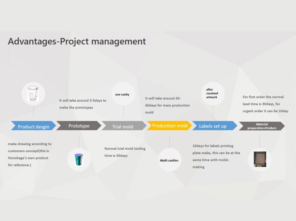
There is no reliable universal lead time. Requirement maturity, revisions, resin supply, geometry, mold metal, cavities, actions, runner, simulation, machining, heat treatment, texture, trials, corrections, testing, approval speed, and plant capacity all matter. Build a milestone schedule by approval gate with owners and review time.
Prepare a useful project review
Send the decisions—not just the model
Share controlled 3D CAD and drawings, material and color, annual and lifetime demand, critical features, cosmetic zones, compliance and validation needs, target schedule, and delivery region. Honokage can review project fit, DFM needs, tooling direction, sampling, and a scoped quotation.
Technical sources
- ISO 20457:2026: Plastics moulded parts—Tolerances and acceptance conditions — current Edition 2 scope for dimensional and geometrical tolerances and acceptance; surface imperfections are outside its scope.
- ISO 294-4:2018: Determination of moulding shrinkage — test-specimen method for molding and post-molding shrinkage, not a finished-part guarantee.
- ASME Y14.5-2018 (R2024) — GD&T language for engineering drawings, models, and related documents.
- Autodesk Moldflow overview — official simulation capabilities for molding design and process risk exploration.
- AIAG: Production Part Approval Process — official PPAP scope for demonstrating conformance during production runs at production rates.
- UL Solutions: Yellow Card Plastics Recognition Program — material-specific recognition and property evidence.
- U.S. FDA: Determining regulatory status of food-contact material components — component identity and intended conditions of use matter.
This guide provides general project-planning information. It does not replace the product owner’s engineering responsibility, supplier-specific DFM, a contract, drawing requirements, risk assessment, or applicable customer, sector, regulatory, laboratory, and validation requirements.