


Symptom · location · cavity pattern · evidence · verified correction
A defect’s appearance is a clue, not proof of its root cause. Short shots, sinks, flash, weld lines, burns, warpage, and ejection damage can each involve the part, mold, material, machine, and process. Record where and when the problem occurs, preserve the baseline, then test one cause category with evidence.
Thermoplastic injection molding troubleshooting guide · Technical review: August 13, 2026
Quick answer
Many common injection molding defects can be linked to imbalances in filling, packing, cooling, venting, ejection, or material preparation. Start by naming the visible symptom and marking its exact location. Compare cavities, lots, shifts, and process history before changing settings.
A short shot at the same last-to-fill rib suggests a different investigation from intermittent short shots across all cavities. Flash at one worn shutoff is different from flash around the whole parting line. A dark mark at an air trap is different from black streaks that appear after long residence time.
The useful rule: classify the pattern, freeze the baseline, inspect low-risk physical causes, test a clear hypothesis, and verify the correction on production-intent parts. Never accept a better-looking sample if dimensions, strength, assembly, or tool risk become worse.
Four rules that prevent random troubleshooting
Diagnosis before correction
Separate the symptom, mechanism, evidence, and action
An injection molding defect is an unwanted condition that makes a part cosmetically unacceptable, dimensionally out of specification, weak, difficult to assemble, unsafe, or inconsistent. A gate vestige, controlled parting line, or agreed ejector witness is not automatically a defect. It becomes a nonconformance when it exceeds the released drawing, visual standard, limit sample, or functional requirement.
Use four levels in every investigation. The symptom is what you can see or measure. The mechanism explains how it may have formed. The evidence supports or rejects that explanation. The corrective action changes the proven mechanism and is followed by verification.
For example, a sink mark is a symptom. Local thick mass, weak packing transmission after gate solidification, or uneven cooling are candidate mechanisms. A thickness map, cavity-level part weight, gate-freeze study, and cooling data provide evidence. “Increase holding pressure” is only an action; it is not proof of root cause.
Defect finder
Common injection molding defects at a glance
Use this table to choose the first investigation, not a universal machine adjustment. The same appearance can have several causes, and a correction can introduce another defect.
| Defect | What it usually looks like | First checks that narrow the cause |
|---|---|---|
| Short shot | Missing edge, rib, boss, or end-of-fill feature | Map last fill; check shot stability, vents, gate restriction, wall thickness, and exact resin grade |
| Weld line | Line where separated flow fronts meet | Compare holes, inserts, gates, and critical zones; test the actual molded part |
| Flow mark / jetting | Ripples or halos; jetting forms a snake-like gate trail | Distinguish patterns; review gate direction, cold slug, initial velocity, and flow-path changes |
| Sink / void | Surface depression or hidden cavity near a thick section | Map thickness; review packing path, part weight, gate solidification, cooling, and gas risk |
| Warpage | Bow, twist, angle error, or unstable assembly fit | Measure by cavity and time; compare cooling, packing, orientation, resin condition, and repeatability |
| Flash | Thin excess plastic at a split, insert, vent, or ejector | Compare cavities and locations; inspect shutoffs; review cavity pressure and clamp capability |
| Burn / streak | Dark end-of-fill mark or streak after downtime | Separate trapped gas from degradation, moisture, shear, or contamination; review vents and history |
| Ejection damage | Whitening, dent, drag, scrape, or crack near ejectors | Map tool location; inspect draft, texture, undercuts, ejector balance, packing, and cooling |
| Specks / unmelted material | Particles, gels, color streaks, or unmelted spots | Preserve sample; check resin lot, regrind, contamination, plasticizing, and hot runner |
| Dimensional drift | Size or weight changes by shot, cavity, lot, or shift | Trend cavity data; check conditioning, cooling, packing, check ring, and measurement method |
“First checks” means evidence that helps narrow a cause family. It is not a universal correction or a substitute for the exact resin supplier’s processing guidance.
Fill and flow defects
What causes short shots, weld lines, flow marks, and jetting?
During filling, the melt must travel through the runner and gate, reach every cavity region before flow stops, displace air through the vents, and meet other flow fronts under suitable conditions. Wall thickness, flow length, gate position, runner balance, venting, resin flow behavior, and the injection profile all influence the pattern.
Short shot: part of the cavity remains unfilled
A short shot is an incomplete molded part. Common candidate causes include a frozen or restrictive flow path, hesitation, a long path, an unvented air pocket, insufficient material delivery, unstable shot volume, or a machine issue such as a worn non-return valve. Low melt or mold temperature may contribute for a specific resin, but temperature should not be raised before the location and stability pattern are understood.
If the same thin rib is missing in every cavity, review actual wall thickness, gate and runner restriction, end-of-fill location, venting, and the selected resin grade. If the defect is intermittent across the tool, trend cushion, shot weight, material feed, drying, check-ring behavior, and the process trace before changing the part.
Weld line: separated flow fronts meet
Weld lines often form downstream of holes, inserts, multiple gates, or unequal flow paths. Their importance depends on position, resin, filler orientation, local temperature and pressure history, appearance requirement, and real loading. A hidden line may still matter in a latch, seal, impact zone, hinge, or pressure boundary.
First map the line against the gate, hole, insert, and expected flow path. Decide whether the risk is cosmetic, structural, or both. Flow analysis can help move the line through gate or wall changes, but it does not prove the finished part’s strength. Validate using the specified resin, color, reinforcement, surface, conditioning, and load.
Flow mark and jetting: two different surface patterns
Flow marks are ripples, halos, or wavelets, often near the gate or end of flow. They may involve cold material, early flow-front solidification, restrictive flow, or weak compensation. Jetting is a snake-like stream created when melt enters too quickly through a restriction or into an open area without contacting the mold wall. Review gate direction and shape, cold-slug control, initial velocity, wall transitions, and hot-runner balance. Do not treat both patterns with the same speed change.

Process evidence
Machine settings are only part of the system
A saved recipe does not prove that the machine delivered the same melt, volume, pressure, or cooling response. Review actual traces and physical output, including part weight and cavity pattern.
Honokage’s live equipment page shows molding and material-handling equipment. For any supplier, the useful question is whether the selected machine, auxiliaries, mold, and monitoring plan can hold the proven window.
Compare pre-change and post-change samples under the same measurement and conditioning method. A recipe adjustment that hides a surface issue but moves dimensions or strength is not a complete correction.
Packing, shrinkage, and cooling
Why do molded parts sink, form voids, warp, or move out of tolerance?
A cavity can look full while the part is still changing. During packing, pressure adds material while a molten path remains open. Cooling then controls local solidification and ejection condition. Unequal thickness, pressure, cooling, or orientation can create shrinkage differences that appear as surface, internal, shape, or dimensional defects.
Sink marks and shrinkage voids
A sink mark is a surface depression. A shrinkage void is a hidden internal cavity. Both can develop near a thick wall, boss, rib intersection, or internal fillet when local contraction is not adequately compensated. If the outer skin yields, the surface may sink; if it remains rigid, the center may form a void. Not every void has this cause, so gas, volatiles, or degradation may also require investigation.
Map the defect to the thickness and distance from the gate. Review whether pressure can reach the feature before the gate or intervening wall solidifies. Compare cavity part weight, packing behavior, cooling, and sectioned or non-destructive evidence where risk justifies it. Coring a boss or reducing local mass can be more robust than forcing the process to compensate for unsuitable geometry.
More holding pressure or time may help only while the flow path can transmit pressure. It may also increase flash, residual stress, dimensions, and ejection force. Establish the project-specific gate-solidification and packing response rather than using a universal setting.
Warpage and dimensional drift
Warpage is a shape error caused by nonuniform shrinkage, cooling, packing, or material orientation. It can appear as bowing, twisting, wavy faces, angle error, or a poor assembly interface. Fiber-filled materials add directional behavior because fiber orientation can make shrinkage different along and across flow.
Measure direction and timing. A part that consistently bows toward one mold side points toward a different check than a dimension that shifts across all cavities after a material lot change. Compare coolant temperature and flow, core-to-cavity balance, gate position, wall transitions, conditioning, resin state, part weight, and machine repeatability. ASTM D955 also warns that shrinkage depends on molding conditions and specimen geometry; a datasheet value cannot predict every complex part.
Tooling and ejection
What causes flash and damage during part removal?
Flash: melt escapes the intended cavity
Flash is a thin excess layer at a parting line, insert, vent, ejector, or shutoff. Possible causes include a damaged or worn sealing surface, poor insert seating, alignment error, mold deflection, insufficient clamp capability, excessive cavity pressure, or a low-viscosity material condition. The exact location is one of the strongest clues.
A local defect in one cavity should trigger tool inspection before a global pressure reduction. More clamp force cannot repair a damaged shutoff or poor alignment. If lower pressure removes flash but creates short shots or sinks, the tool, gate, part, and process may not share a capable window.
Ejector marks, drag, whitening, and cracks
Map the mark to the mold and ejection system. Review draft, texture direction, undercuts, scratches, polish direction, vacuum release, ejector contact area, and balance. Also check whether overpacking increases grip or early ejection leaves the part too soft.
A delayed crack may involve residual stress, weak weld lines, environmental exposure, or differential shrinkage rather than the visible ejector alone. Verify the correction using cosmetic lighting, dimensions, assembly force, and the real load or chemical condition.
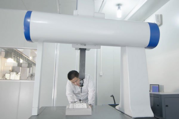
Tool construction and maintenance can affect shutoffs, vents, gates, cooling, alignment, texture, and ejection. This image illustrates equipment, not a specific defect.
Gas, heat, and material clues
A dark mark or streak is not one universal defect
A dark end-of-fill mark can come from compressed trapped air heating the polymer. Dark streaks after a stop may point toward degradation from excessive residence, temperature, shear, or a dead spot. Silver streaks may involve moisture or other volatiles for a specific resin, but restrictive flow, shear, contamination, or material inconsistency can create similar appearances.
Preserve and label the sample. Record the cavity, location, startup or downtime history, resin grade and lot, color, approved regrind, dryer record, purge history, and actual process trace. Inspect vents, runner and hot-runner dead spots, restrictions, material feed, and plasticizing condition. Use the exact material supplier’s drying and restart guidance; not every resin uses the same drying method.
Unmelted particles, sometimes called fish eyes in factory practice, are different from every black speck or gel. Confirm whether the feature is unmelted resin, an incompatible blend, excessive or inconsistent regrind, pigment agglomerate, degraded material, or external contamination.
IML containers can also show label misplacement, wrinkles, bubbles, print defects, or poor label integration. Those are related but need a label, static or vacuum, robot, mold, resin-flow, and artwork investigation. They should not be collapsed into a generic resin-defect recipe.
Root-cause workflow
Use these seven steps before approving a correction
- Contain and classify. Separate suspect output, name the symptom, and decide whether safety, fit, strength, sealing, or appearance may be affected.
- Map the pattern. Mark orientation, gate distance, tool feature, cavity, cycle stage, lot, shift, and first appearance.
- Freeze the baseline. Save known-good and failed samples, settings, actual traces, part weight, material records, and inspection conditions.
- Check physical clues. Inspect vents, gates, shutoffs, cooling, ejection, feed, dryer, contamination risks, and machine repeatability.
- Test a hypothesis. Predict what one change should improve and what tradeoff it might create. Use a planned experiment when variables interact.
- Verify at production intent. Run the approved grade, tool, machine, cavities, cycle, automation, and inspection method long enough to expose normal variation.
- Lock the learning. Update the process window, maintenance, drawing or visual standard, control plan, training, and change record.

Coupled-defect example
A sink near a boss may improve with stronger packing, yet flash can appear at a worn shutoff and ejection force can rise. That result does not prove the new recipe is robust.
Separate temporary containment from permanent correction. The lasting action may require local geometry, gate, cooling, or tool repair. Then recheck sink, flash, dimensions, residual stress, cycle, and every required cavity together.
Buyer-side prevention
Define acceptance before the first production order
A supplier cannot manage an unwritten definition of “looks good.” Release the drawing, datums, critical dimensions, conditioning method, functional tests, and approved material. Identify cosmetic zones and state lighting, viewing distance, angle, gloss, texture, color method, and limit samples. Agree what gate, ejector, and parting-line witnesses are acceptable.
Ask the molder to report the exceeded requirement, affected cavities and lots, exact defect location, recent changes, evidence supporting the cause, temporary containment, permanent action, expected tradeoffs, and verification result. Honokage’s quality workflow provides context for inspection; this article explains how to turn a failed result into a disciplined investigation.

Release evidence
A correction is complete only when the part stays acceptable
Confirm the original defect has fallen within the written limit and that the action did not damage another requirement. Use cavity-level records, not only pooled averages. Include startup, steady production, approved interruptions, and restart when those conditions matter.
Measurement system, sample size, run length, and stress testing should follow the failure risk. Simulation and first-off parts guide decisions, but production-intent evidence releases the process.
Domande frequenti
Common questions about molding defects
What is the most common injection molding defect?
There is no reliable universal winner. The dominant defect depends on part geometry, resin, mold, process window, equipment condition, and acceptance standard. A cavity-level Pareto chart for your product is more useful than an industry guess.
Will more holding pressure remove every sink mark?
No. Pressure helps only while a molten path can transmit it to the thick area. More pressure may add flash, stress, dimensional change, and ejection load. Geometry, gate timing, and cooling may need correction.
Are weld lines always unacceptable?
No. Acceptance depends on location, visual limit, resin, reinforcement, load, environment, and test evidence. A weld line in a high-load latch or seal needs different proof from one in a hidden, low-stress area.
Why can flash appear suddenly after stable production?
Check the exact location and recent history. Wear, debris, insert seating, alignment, vent or shutoff damage, material change, cavity-pressure shift, machine behavior, or mold-temperature change may be involved.
Should a troubleshooting trial change only one variable?
One controlled change makes cause and effect easier to read. When factors interact, use a planned design of experiments. In both cases, define the prediction and measure all important outputs.
How can a buyer avoid appearance disputes?
Agree cosmetic zones, inspection setup, named defect limits, approved boundary samples, sampling, and escalation before production. Photographs help communication but should not replace controlled physical standards when color, gloss, texture, or depth matters.
Prepare a useful DFM or defect review
Send the part evidence, not just the defect name
Share the CAD or drawing, exact material grade, defect photos with scale and orientation, affected cavities, known-good and failed samples, annual volume, acceptance standard, and any material, tool, machine, or process change. Honokage can use this package for a focused engineering and mold review.
Technical sources
Engineering boundaries were checked against BASF’s injection molding troubleshooting guide, Autodesk guidance for short shots, weld lines, sink marks and voids, burn marks, and ASTM’s D955 molding shrinkage standard. Always use the current applicable edition, exact material guidance, and project-specific requirements.